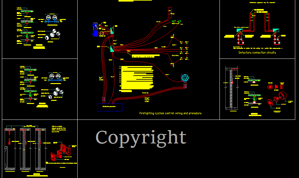
Firefighting pumps room wiring and control diagram. Including detectors and control panel (external simple connection wiring)

Firefighting System Control 17 notes, will appear upon purchase.

Copyright, so you cannot resell or distribute it.

Add to wish list
Gallery Images
Plan Category
Units
File Type
Materials
Units
Download Notes Firefighting System Control 1. When a fire appears in presence of any employee, first use a fire extinguisher (FE) if the fire is small. Noting that small FE 9 kg can last 10 seconds only, where 12-15 kg can last 14-17 seconds. 2. If (1) cannot solve the issue, the worker can use the fire hose cabinet (FHC), hose of 40mm or 1 ½” (4.5 bars) or for a trained person 65 mm (2 ½”) 6.9 bars. The pump will be turned on automatically. 3. The pump turns on automatically: When the pressure is reduced by any means such FHC hose is opened. The electronic pressure sensor in the discharge collector will mark that the pressure is dropped below a certain value (regulate the difference at 1.5 bar to 2 bars) from the original 10 bars. 4. To set a pre-set water-pump pressure in the system, regulate first the automatic pressure relieve valve (PRLV) in the pump room and set it between 10 to 11 bars (check the pressure gauge PG accordingly). The pump has 500 gpm which is a big flow, and there is no jockey pump. So, any excess in pressure, the PRLV will release and maintain the pressure at a set value. 5. Hose opened: Water will fall and the pressure will be reduced, the ePG will detect that the pressure dropped to a trigger point of pressure and send a signal to the control panel (to control module) and reply to the monitor module to let people informed what is happening. Then the dedicated generator to the firefighting system shall be turned on automatically, and then the pump will be turned on after the time of period which they are safe to let the pump withdraw current from this generator (usually 10to 20 sec.). In case there is no other electricity source (such as other generators, which usually are turned on). In case if there is another current, and the electricity is still generated from the factory generators, the pump shall be turned on for a few seconds until the dedicated generator is ready, the pump electricity source shall be switched to the dedicated generator. 6. The control panel: Is a control panel of the entire system including a battery, control module, and monitor module. Communicate voltage is 24 V and 3phase for power. 7. If the above procedure (3) is failed by a test, we can add a pushbutton inside a FHC to force the pump to turn on. 8. Once the pump is turned on, a signal will send to horns as an alarm and for the sign “Exit” if it is installed as wired signed. Otherwise, cannot be used as a battery, but simply as a panel of 2m x 0.8m with phosphoric font color in a yellow plaquette. 9. In case a fire occurred in absence of any person: if the fire occurs in wood or polyurethane foam blocks, the fire reaches a detectable state after 90 seconds. There is some possibility and because the reason is the sensors are installed at a high level (let to say 6 to 8 m, except cutting area and the 1st floor, is around 4 m). The smoke detectors are better than temperature detectors in this case. And since the detectors are spaced around 9m the smoke needs 90 sec. to 5 minutes to trigger the detector. Another system will be installed in parallel smoke beam detectors to catch the smoke at low levels and at long distances. One a detector, send a signal about a fire… 10. A detector sends a signal to the control module, and the loop circuit as per design helps to double protect the system. Any break of the loop can detect from the other side. After getting a signal of a fire it will be shown on the monitor module and a signal send to horns speakers and a current outage shall be occurred by sending a signal of 24 V to the operating bobbin-disjunctor of the related space to cut-off the current there. The generator dedicated to the fire system will turn-on automatically via the control module. After a few seconds (the safe time to start using the generator, [10,20] sec.), the pump will be turned on automatically. If no hose is opened, the system will be pressured at a set pressure of 4” PRLV, any excess will go back to the suction line of the pump. In the future, if a diesel pump is added, a Jokey shall be too, due to SP sprinklers being added and the control will change too. As per procedure (5) above, the pump shall operate on the other current source for 20 sec, to switch to the dedicated generator to this system. 11. If the factory will operate at night, emergency lights will be added or some of the existing lamps shall be connected to a UPS system to still on in an emergency case. 12. Fire pump safety: PRLV should be installed, switching between electricity sources to be as described above. The fire pump shall have a magnetic disjunctor rated 2.5 times the pump current. 13. Starting from step (10), if the circuit of the production cutting area or cutting roll area (the first floor) sent a signal to the control module, step (10) is verified in addition to the following steps. If the fire occurs in the production cutting area, the three 3 fans shall be turned, first the lower one, then after a few seconds, the two others in sequence (they are located in the ceiling of the 1st floor). If the fire occurs on the 1st floor, only the two upper fans shall be turned on. 14. Note: An image of the monitor module shall be existing in the office of a responsible person, to check which space is in the fire. 15. Remark about the push button inside the FHC: If the automatic ePG failed to start the pump, a new support system shall be installed. The test should be done and the commissioning to be done by an engineer. If the system needs this push button since the pump is 3 phases, we need only 0.75 square mm of wire to connect detectors and this pushbutton, they can be in the same circuit, each zone or space in its own circuit. Horns should be connected by 1.5 square mm or as per manufacture recommendation. Once the push button is pressed, a signal is received to the control panel module and it works like a smoke detector signal, the generator first then the pump to be turned on as the steps above. If a button is pressed again in the same zone, the pump shall be turned off, followed by the generator. 16. The curb mounting fan on the roof, shall be turned off if a fire happened, because the entrance doors of each space cannot be closed, so the entrance of oxygen feeds the fire. So, the control panel shall turn off all the fans except the new fans which should be installed in the next stage. The curb-mounted fans (Cyclones-shaped fans) on be turned on when the fire terminates and to remove smoke. 17. Best solution to solve uncontrollable doors by the fire system, when a fire happens on production cutting area and in the 1st floor, the fan shall be turned on as in note (13), until all worker are escaped. Better to turn it off from the control panel manually, to avoid feeding oxygen to the fire in these two spaces (only).
Terms and Conditions I agree

You must log in to submit a review.